In most industrial boiler rooms across Kenya, a sudden burner lockout at 3:00 AM follows a predictable script. The plant supervisor notices steam pressure dropping on the line, walks over to the boiler, sees the control box glowing bright red, presses the reset button, and listens. The motor spins, the fan purges, the ignition transformer buzzes, but there is no flame. The burner trips out again on safety lockout.
Nine times out of ten, the first component blamed is the fuel pump. A spanner is fetched, the technician begins turning the pressure adjustment screw clockwise hoping to force oil through, and when that fails, someone declares the pump dead.
Sometimes the pump is indeed worn out. But in our experience across processing plants in Nairobi Industrial Area, tea factories in Kericho, and bakeries in Thika, half of the fuel pumps replaced have nothing mechanically wrong with them. They were simply starved of oil, choking on cold paraffin sludge, or venting through a destroyed shaft seal because a five-centimeter bypass plug was installed in the wrong port.
Understanding how a gear pump actually moves oil, builds pressure, and regulates atomization makes the difference between an accurate twenty-minute repair and days of unnecessary production downtime.
How Burner Fuel Pumps Build Pressure
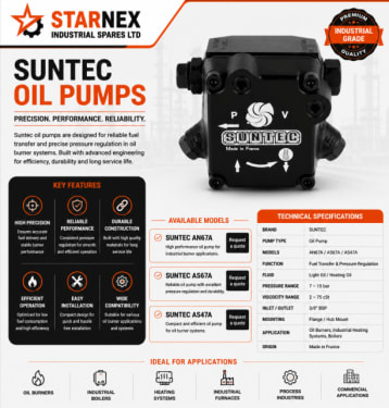
Industrial pressure-jet oil burners—whether fired by diesel (Automotive Gas Oil / AGO), kerosene, or light fuel oil—rely on a positive displacement gear pump manufactured by companies like Suntec, Danfoss, or RBL.
The pump does two separate jobs:
- 1Suction & Delivery: The rotating internal gear set creates a vacuum at the suction port, pulling fuel from the daily service tank through the pipeline filter and forcing it into the pump chamber.
- 2Pressure Regulation & Cut-off: A built-in spring-loaded diaphragm or piston valve regulates delivery pressure to the burner nozzle (typically between 10 and 14 bar for standard light oil nozzles). When the burner stops, an internal cut-off valve or an integrated solenoid valve closes instantly, preventing unburned fuel from dribbling into the hot combustion chamber.
When pressure drops below the minimum threshold required to crack open the nozzle assembly, atomization fails. Instead of a fine, fog-like spray pattern that ignites easily, fuel squirts out in coarse droplets or fails to leave the nozzle tube entirely. The flame sensor sees nothing, and the burner control box shuts down the system.
Burner Fuel Pump Failure Diagnostic Matrix
Before removing fuel lines or adjusting screws, run through this symptom matrix to isolate the true root cause:
| Observed Symptom | Probable Root Cause | Immediate Verification Step | Corrective Action |
|---|---|---|---|
| Whining or screeching sound during motor run | Hydraulic cavitation; excessive suction vacuum exceeding 0.4 bar | Inspect vacuum gauge on suction line; check pre-filter bowl | Clean fuel strainer; open supply valve; check for line blockages |
| Gauge pressure reads 0 bar; motor turning | Stripped drive coupling; sheared drive shaft key; incorrect shaft rotation | Disconnect pump from motor; verify nylon coupling sleeve is intact | Replace drive coupling; confirm rotation direction matches motor |
| Pressure drops gradually over 10–30 minutes | Internal mesh strainer clogged with fine rust or paraffin wax | Remove pump cover screws; inspect cylindrical mesh element | Wash filter element in clean kerosene or replace mesh screen |
| Diesel dripping from burner housing or motor shaft | Mechanical lip seal failure due to wear or over-pressurized return line | Check weep hole behind mounting hub; look for oil wetting on motor | Replace complete pump assembly; check for unvented return line |
| Fluctuating pressure gauge needle (±2 bar) | Air ingress on suction line fittings; low oil level in daily tank | Check oil lines for bubbles; test fittings with soapy water or vacuum | Tighten flexible hose unions; bleed air via pressure port |
| Burner smokes heavily; unburned fuel smell | Pressure set too low causing poor atomization, or worn nozzle | Connect 0–25 bar gauge to 'P' port; check actual firing pressure | Adjust regulator to manufacturer spec; replace worn burner nozzle |
The Four Most Common Fuel Pump Failure Modes
1. Suction Line Restriction and Cavitation
When oil cannot reach the pump chamber as fast as the rotating gears attempt to displace it, the pressure inside the gear pocket drops below the vapor pressure of the fuel. Microscopic vapor bubbles form and collapse violently against the metal teeth under thousands of pounds of localized hydraulic force. This phenomenon is cavitation.
In high-altitude areas like Limuru, Eldoret, or Mount Kenya regions, cold nighttime temperatures significantly increase the viscosity of diesel and light fuel oil. If your daily tank sits outside without heat tracing, or if your primary water-trap pre-filter is partially choked with microbial sludge, the pump will cavitate, whine loudly, and deliver erratic, surging pressure.
Rule of Thumb: Clean your pre-filters and check line vacuum before touching the pump's pressure regulator. Suction vacuum should never exceed 0.4 bar (12 inHg).
2. Clogged Internal Mesh Strainer
Almost every Suntec (AN, AS, AL series) and Danfoss (BFP series) pump contains an internal wire-mesh strainer located directly beneath the top cover plate. While plant technicians regularly clean the external pre-filters on the wall, many forget that the pump itself houses a second, much finer filter.
When this internal mesh fills with scale from black steel pipework or fine particulate, fuel flow drops. The pressure gauge needle will read normal pressure for the first few seconds of firing, and then slowly drift down toward zero as the chamber starves. Removing the top four Allen bolts, extracting the cylindrical screen, and cleaning it with a soft brush and clean solvent restores full flow in minutes.
3. Shaft Seal Failure and External Leakage
The drive shaft that connects the electric motor to the internal gears is sealed by a high-temperature synthetic rubber lip seal. Under normal operating conditions, this seal lasts thousands of operating hours. However, two things destroy it rapidly:
- •Operating Dry: Running the pump without oil during startup or bleeding generates intense friction heat on the shaft lip, burning the elastomer in seconds.
- •Return Port Over-Pressurization: In a two-pipe installation, the return line carries excess oil back to the tank. If someone leaves a shutoff valve closed on the return line, or kinks the flexible return hose, back-pressure pushes directly against the shaft seal lip, blowing oil into the motor housing.
If diesel is pooling beneath the burner or misting inside the fan housing, the shaft seal has failed. Do not continue running the burner; diesel vapor drawn into an electric motor creates a severe fire hazard.
4. Pressure Regulator Spring Fatigue and Debris Seating
Inside the pump's pressure adjustment housing sits a precision spring and a hardened steel piston or diaphragm. When you turn the adjustment screw clockwise, you compress the spring, requiring higher hydraulic pressure before the valve lifts to bypass fuel back to the return line.
Over years of continuous operation, this spring can experience fatigue, causing delivery pressure to sag. More frequently, tiny flecks of pipe scale or hardened carbon lodge between the valve seat and the piston face. When this happens, the valve cannot seat tightly; fuel continuously leaks into the bypass channel, and delivery pressure to the nozzle drops below firing requirements.
One-Pipe vs. Two-Pipe Systems: The Deadly Bypass Plug
One of the most frequent installation errors encountered by our technical counter team involves the internal bypass grub screw.
Suntec and Danfoss fuel pumps leave the factory configured for a two-pipe installation (one suction line, one return line). In this configuration, an internal bypass plug (a small threaded socket grub screw) is installed deep inside the return port. This plug closes off the internal return passage, forcing excess oil out through the return pipe back to the supply tank.
- •In a Two-Pipe System: The bypass plug must be installed. Return oil flows freely through the second pipe back to the supply tank.
- •In a One-Pipe System (Gravity Feed): The bypass plug must be removed! In a single-pipe setup, there is no return pipe connected to the tank; the return port is sealed with a solid plug. If the internal bypass grub screw is left inside the pump, bypassed fuel has nowhere to go. Pressure spikes instantaneously inside the casing, and the shaft lip seal blows out within five seconds of motor rotation.
SAFETY CRITICAL: Always read the technical installation leaflet packaged with your new pump. If your burner has only one fuel hose connecting it to the tank, verify that the internal bypass plug has been removed before switching on electrical power.
Understanding Model Codes Before Ordering
When ordering a replacement pump from STARNEX in Nairobi, simply asking for "a Suntec burner pump" is not enough. Suntec alone produces dozens of variants that look almost identical externally but will not function on your machine if the rotation or porting is mismatched.
Consider the common model designation Suntec AS 47 A 7432 4P:
- •AS: Model series (integrated solenoid valve with cut-off function).
- •47: Gear capacity (delivers approximately 40–50 L/h at nominal pressure).
- •A: Rotation direction and nozzle outlet location:
- •A: Clockwise rotation (R), Right-hand nozzle outlet.
- •B: Clockwise rotation (R), Left-hand nozzle outlet.
- •C: Counter-clockwise rotation (L), Left-hand nozzle outlet.
- •D: Counter-clockwise rotation (L), Right-hand nozzle outlet.
- •7: Version / generation code.
- •432: Internal design and valve configuration numbers.
- •4P: Solenoid valve coil connection type and mounting style.
          LOOKING DIRECTLY AT THE PUMP SHAFT END:
                        [TOP COVER]
                           ┌───┐
                           │   │
           Left Port ◄─────┤ P ├─────► Right Port
           (Models B & C)  │ U │      (Models A & D)
                           │ M │
                           │ P │
                           └───┘
                         [MOUNTING]
                Rotation: Clockwise (R) or Counter-Clockwise (L)
If you install a model C pump where an A was originally fitted, the drive shaft will turn in reverse. The pump will draw air from the nozzle port and deliver zero fuel.
Step-by-Step: How to Test and Adjust Fuel Pressure Correctly
Never adjust burner fuel pressure by eye or by listening to the sound of the flame. The only reliable method requires a calibrated pressure gauge.
- 1Safety Isolation: Switch off the main electrical isolator to the boiler burner control panel.
- 2Remove Blanking Plug: Locate the pressure gauge port on the pump casing, clearly stamped with a letter 'P' (usually a 1/8" or 1/4" BSP female thread). Using an Allen key, remove the steel blanking screw.
- 3Install Gauge: Thread a 0–25 bar glycerin-filled pressure gauge with a copper crush washer into the 'P' port. Snug it down firmly; do not overtighten brass threads into cast aluminum.
- 4Purge Air: Connect an open hose from the vacuum/pressure test port to a clean container to bleed trapped air during initial priming.
- 5Start Burner: Restore power and initiate the burner start sequence. Once the burner reaches main flame, observe the gauge needle.
- 6Adjust Pressure: Remove the protective cap over the pressure regulator screw. Using a screwdriver or Allen key, turn slowly:
- •Clockwise: Increases delivery pressure (increases firing rate and fuel droplet velocity).
- •Counter-Clockwise: Decreases delivery pressure.
- •Target: Adjust to the exact specification specified on the boiler technical data plate (typically 11–13 bar for standard diesel burners).
- 1Lock and Verify: Reinstall the protective cap. Switch the burner off and allow it to restart automatically. Verify that pressure builds smoothly and cuts off cleanly without needle chatter.
What Information to Provide STARNEX for Replacements
If your pump has suffered mechanical seizure, worn gear teeth, or damaged internal castings, our trade counter at Enterprise Road, Nairobi maintains ready stock of Suntec, Danfoss, and RBL pumps for immediate dispatch across Kenya, Uganda, and Tanzania.
To ensure you receive the exact drop-in replacement on the first attempt, have the following details ready:
- •Nameplate Photo: Send a clear WhatsApp photo of the stamped aluminum tag on top of the pump to our technical desk at +254 740 459 672.
- •Shaft Diameter & Hub Size: Measure the drive shaft diameter (typically 8 mm with a single flat) and mounting collar diameter (standard 32 mm or 54 mm flange).
- •Burner Brand & Model: E.g., Riello 40 G10, Baltur BTL 14, Weishaupt WL20, or Ecoflam Max 12.
- •Coil Voltage: If the pump has an integrated solenoid valve, check the voltage stamped on the coil (220–240VAC 50Hz, 110VAC, or 24VDC).
If you are dealing with persistent pressure drops or noisy pump operation, contact the STARNEX technical engineering desk for guidance on system diagnostics before ordering replacement assemblies.