On an industrial burner control panel, no light is more universally dreaded by a boiler operator than the solid red square illuminated in the center of the reset button. When that button glows red, it means the burner control box has initiated a safety lockout. The fuel valve has slammed shut, the ignition spark has ceased, and the steam line is cooling down.
In factories across Nairobi Industrial Area, Athi River, and Mombasa, the instinctive reaction is often brute force: press the reset button. If it trips again after twenty seconds, press it again. If it trips a third time, press and hold it down.
Modern microprocessor-based burner controllers manufactured by Siemens—specifically the LMO series for oil burners and the LME series for gas and dual-fuel burners—are not simple electromechanical timers. They are safety-certified computers. They monitor every millisecond of the combustion sequence. When they lock out, they do not just stop; they record the exact failure mode in memory.
Instead of resetting blind, learning how to read the optical flash codes and understanding terminal base pinouts allows you to pinpoint the exact failure in the ignition chain within two minutes.
The Combustion Sequencing Cycle
To understand why a Siemens controller trips, you must understand the five distinct phases of the automated burner sequence:
- 1Standby (Tw): The control box receives 230VAC power across terminals 1 (Neutral) and 2 (Live). The operating thermostat or pressure switch on terminal 3 closes, signaling demand for heat.
- 2Pre-Purge (t1): The burner fan motor starts via terminal 4. The fan forces fresh air through the furnace flues to expel any lingering fuel vapors left from previous firing. In gas burners, the air pressure switch must prove airflow within a fixed window (t10).
- 3Pre-Ignition (t3): The ignition transformer energizes via terminal 3 or 6, generating a 10,000-volt high-frequency electrical arc across the ignition electrode tips.
- 4Safety Time (t2): The stage-1 fuel solenoid valve opens via terminal 8. Fuel atomizes from the nozzle into the electric arc, producing a flame. The flame detector (photocell on oil, ionization rod or UV sensor on gas) must detect a stable flame signal within safety time t2 (typically 5 to 10 seconds).
- 5Main Run: Once flame is verified, the ignition spark de-energizes. The burner settles into normal modulated or two-stage firing until the boiler reaches target steam pressure.
If any condition in this sequence fails—such as lack of air, weak flame signal, or extraneous light before spark—the controller cuts power to the fuel valve within 1 second and locks out.
Optical Lockout Flash Code Diagnostic Table
When a Siemens LMO or LME controller locks out, the reset button glows solid red. To enter optical diagnosis mode, press and hold the reset button for longer than 3 seconds.
The red LED will blink off, then begin flashing a repeating sequence of red pulses followed by a 2-second pause. Count the pulses between pauses:
| Number of Red Blinks | Error Classification | Probable Root Cause in Combustion Chain | Diagnostic Check Step |
|---|---|---|---|
| 2 Blinks | No flame established at end of safety time (t2) | Clogged fuel nozzle; air in fuel line; fouled ignition electrodes; dirty photocell | Inspect photocell lens; verify 12 bar fuel pressure; check spark gap |
| 3 Blinks | Air pressure failure (LP / HP switch) | Combustion air pressure switch did not close during pre-purge or opened during run | Check fan blower wheel for lint; clear silicone pressure switch tubes |
| 4 Blinks | Extraneous light during pre-purge (t1) | Glowing refractory brick in combustion chamber; shorted photocell cable | Remove photocell; inspect sensor dark resistance; check firebox glow |
| 7 Blinks | Loss of flame signal during normal operation | Fuel starvation (air bubble in line); contaminated oil; unstable draft pressure | Check fuel pre-filter; verify chimney damper setting; clean nozzle filter |
| 10 Blinks | Internal wiring or electronics error | Short circuit on auxiliary terminal output; line voltage surge exceeding 264VAC | Check base terminal wiring for shorted strands; test supply voltage |
To exit diagnosis mode and return to standard operating lockout, press the reset button again for approximately 1 second.
Siemens LMO vs. Siemens LME: Key Engineering Differences
While LMO and LME controllers share the same standard rectangular footprint and plug into identical Siemens AGK11 base receptacles, their internal circuitry and logic firmware are fundamentally different:
| Parameter | Siemens LMO Series | Siemens LME Series |
|---|---|---|
| Approved Fuel Types | Diesel (AGO), Kerosene, Light Distillate Oils | Natural Gas, LPG, Biogas, Dual-Fuel |
| Primary Flame Sensor | Photocell (QRB1, QRB3, QRB4) or Blue Flame (QRC) | Ionization Flame Rod or UV Sensor (QRA2, QRA10) |
| Air Proving Supervision | Optional in light oil; relies primarily on motor run | Mandatory air pressure switch supervision (Dungs/Kromschroder) |
| Typical Models in Kenya | LMO14.113C2, LMO24.255C2, LMO44.255C2 | LME11.330A2, LME21.330A2, LME22.232A2 |
| Post-Purge Capability | Fixed or disabled on basic models | Configurable post-purge via auxiliary terminals |
| Actuator Control | Direct relay outputs for 1-stage or 2-stage valves | Integrated servomotor cam control (SQN31 / SQN72) |
CRITICAL WARNING: Never substitute an LMO oil controller onto a gas burner. Gas combustion requires strict air proving and ionization rectification standards that oil controllers do not provide.
Upgrading from Landis & Gyr LOA24 to Siemens LMO24
Thousands of legacy package burners across East Africa—including older Riello, Baltur, and Weishaupt units installed in the 1990s and 2000s—were equipped with electromechanical Landis & Gyr LOA24 controllers.
Because Landis & Gyr was acquired by Siemens, the mechanical LOA series was discontinued and superseded by the solid-state Siemens LMO24.255C2. Upgrading is direct and straightforward:
- 1Base Compatibility: The LMO24 plugs directly into the existing black Bakelite AGK11 base without changing terminal positions.
- 2Lower Power Consumption: The solid-state LMO24 draws significantly less current during standby and eliminates the mechanical bimetallic timer that eventually jammed in the LOA24.
- 3Photocell Considerations: Older LOA24 boxes frequently operated with high-resistance photocells. If the flame signal is marginal after installing an LMO24, replace the sensor with a modern Siemens QRB1-A photodiode, which offers high sensitivity to yellow diesel flames.
                  SIEMENS AGK11 BASE TERMINAL MAP:
   ┌─────────────────────────────────────────────────────────┐
   │  [1] Neutral Supply (N)                                 │
   │  [2] Live Supply 230VAC (L) via Safety Thermostat       │
   │  [3] Operating Control Thermostat / Pressure Switch     │
   │  [4] Burner Fan Motor / Air Proving Switch              │
   │  [5] Auxiliary Fan Contactor (Optional)                 │
   │  [6] Ignition Transformer Line                          │
   │  [7] Auxiliary / Remote Lockout Alarm Indication        │
   │  [8] Stage 1 Fuel Solenoid Valve                        │
   │  [9] Stage 2 Fuel Solenoid Valve (LMO24 only)           │
   │  [11/12] Photocell / Flame Detector Signal Return       │
   └─────────────────────────────────────────────────────────┘
The Lethal Mistake: Bridging Terminals to Bypass Lockout
When a factory faces severe production pressure and the burner controller repeatedly trips on safety, an untrained technician may be tempted to bridge terminals on the wiring base—most commonly placing a jumper wire between terminal 3 (thermostat line) and terminal 8 (fuel valve).
Never do this under any circumstances.
When you bridge terminal 3 to terminal 8, you bypass the forced pre-purge cycle. If atomized fuel oil was sprayed into the furnace during the previous failed attempt, the combustion chamber is already saturated with volatile hydrocarbon vapor. When the ignition transformer fires without purging that vapor, the entire firebox explodes.
In steam boilers, an explosion inside the flue tubes can dislodge refractory doors, buckle smoke tube sheets, and cause catastrophic injury to personnel in the boiler house. The control box locks out for a reason: identify and fix the underlying ignition fault.
Sourcing the Correct Controller at STARNEX Nairobi
To ensure you receive the exact drop-in controller for your boiler or industrial furnace, bring or WhatsApp the following details to our technical team:
- •Model Code on Housing: E.g.,
LMO24.255C2(indicates 2-stage oil, 230VAC, 5s safety time, 25s pre-purge). - •Base Requirements: Specify whether you require the bare controller body or the complete assembly with the AGK11 wiring base and cable clamp bracket.
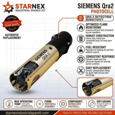
- •Flame Sensor Matching: Confirm whether your system uses a yellow-flame photocell (QRB1/QRB3), a blue-flame sensor (QRC), or an ultraviolet tube (QRA2).
STARNEX supplies genuine, factory-boxed Siemens combustion controllers with E-TIMS tax invoices and same-day delivery across Nairobi, Mombasa, Kisumu, Kampala, and regional industrial hubs.