In an industrial gas-fired boiler, commercial bakery oven, or glass annealing kiln, gas safety is not negotiable. While a malfunctioning oil burner produces unburned soot, heavy smoke, and foul odors, an uncorrected gas leak is invisible, odorless, and potentially catastrophic.
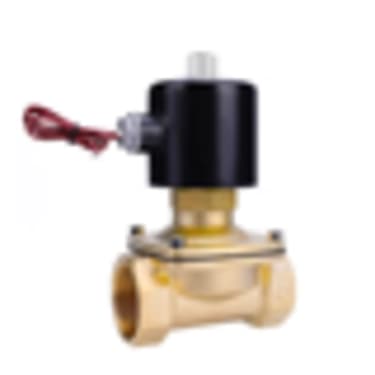
At the heart of every gas burner fuel delivery train sits a pair of electromagnetic shut-off valves: the gas solenoid valves (often referred to as Safety Shut-Off Valves, or SSOVs). Their job is absolute and uncompromising: when electrical power is cut—whether by the burner thermostat, the boiler high-limit pressure switch, or an emergency stop button—the valves must slam shut in less than one second, creating a hermetic, gas-tight seal against system pressure.
Yet across industrial plants in Kenya, gas valves are often operated for years without periodic seat tightness verification. Over time, microscopic pipe scale from black steel headers, welding slag, and elastomer hardening compromise the valve seat. Gas slowly creeps past the closed disc, pooling in the bottom of the cold boiler furnace.
When the burner control box initiates the ignition cycle after an overnight shutdown, that accumulated gas ignites in an instantaneous, violent detonation that can blow the explosion relief doors off their hinges.
Regular leak testing of gas solenoid valves is not just good maintenance practice; it is a fundamental life-safety requirement.
The Architecture of a Certified Industrial Gas Train
Under international combustion safety standards (such as EN 676 and NFPA 86), a single gas solenoid valve is never legally sufficient on an automatic burner exceeding 30 kW capacity. Certified gas trains utilize a Double Block safety configuration:
                  CERTIFIED DOUBLE-BLOCK GAS TRAIN ARCHITECTURE:

   Gas Inflow         Manual      Gas      Pressure      Valve 1       Intermediate       Valve 2       Burner
  (LPG/Nat Gas) ──►  Cock (Ball) ─► Filter ─► Regulator ─►  (SSOV)  ──►  Test Cavity   ──► (SSOV) ──►   Head
                                                             ▲               ▲               ▲
                                                             │               │               │
                                                     Fast-Closing     Test Point /     Fast-Closing
Safety VPS Port Safety- 1Manual Main Cock: Quarter-turn ball valve for emergency physical isolation.
- 2Gas Filter: Upstream basket filter (typically 50-micron) to catch particulate matter.
- 3Gas Pressure Regulator: Stabilizes pipeline pressure down to operational burner manifold pressure (e.g. 20 to 100 mbar).
- 4Safety Valve 1 (V1): Fast-opening or slow-opening automatic safety valve.
- 5Intermediate Cavity: Monitored chamber between V1 and V2.
- 6Safety Valve 2 (V2): Second safety shut-off valve with integrated flow volume adjustment.
By placing two valves in series, if one valve fails to seat cleanly due to a piece of trapped rust, the second valve maintains complete mechanical containment.
Class A vs. Class B Solenoid Valves: Understanding Standards
Burner gas solenoid valves are certified according to European Standard EN 161:
| Classification | Closure Response Time | Maximum Allowable Internal Leakage Rate | Mandatory Field of Application |
|---|---|---|---|
| Class A | < 1.0 Second | < 0.1 Litres/Hour (Under Max Pressure) | Mandatory for all industrial boilers, process heaters, and forced-draft burners |
| Class B | < 1.0 Second | < 1.0 Litres/Hour | Permissible only on small atmospheric domestic appliances |
| Class C / D | < 3.0 Seconds | Higher leakage allowances | Obsolete in modern industrial combustion installations |
PROCUREMENT STANDARD: When ordering replacement gas valves from STARNEX, ensure you specify EN 161 Class A compliance. Using unrated general-purpose fluid solenoid valves on a combustible gas line violates safety standards and invalidates plant insurance policies.
Step-by-Step: The Manual Bubble Leak Testing Procedure
While high-end modern burners feature automated electronic leak detection, every maintenance engineer must know how to perform a physical manual seat tightness test during scheduled boiler servicing:
                     MANUAL BUBBLE LEAK TEST RIG:
                          [ Valve 1 ]        [ Valve 2 ]
                             (V1)               (V2)
                              ┌───┐              ┌───┐
        Gas Pressure ─────────┤ X ├──────┬───────┤ X ├────────► Closed
                              └───┘      │       └───┘          Downstream Valve
                                         │ Test Nipple
                                         ▼
                                 Flexible Rubber Hose
                                         │
                                         ▼ (Submerged 10 mm)
                                    ┌─────────┐
                                    │ ~ ~ ~ ~ │  <-- Clear Water Beaker
                                    │  [•]    │  <-- Zero Continuous Bubbles Permitted
                                    └─────────┘
Step-by-Step Test Sequence:
- 1Isolate Power: Ensure electrical power to both solenoid coils is disconnected so both valves remain fully closed.
- 2Close Downstream Cock: Close the manual ball valve closest to the burner nozzle head.
- 3Connect Test Hose: Remove the 1/8" BSP brass plug on the test nipple situated in the cavity between V1 and V2. Push a clear 6 mm flexible plastic tube firmly over the barbed fitting.
- 4Submerge Tube: Lower the open end of the tube into a clear beaker of clean water so the tip is submerged exactly 10 mm below the water surface.
- 5Pressurize Upstream: Slowly open the manual gas inlet cock upstream of V1. Operating gas pressure now pushes against the closed seat of Valve 1.
- 6Observe for Bubbles:
- •Initial displacement bubbles may appear as air inside the test tube expands. Wait 30 seconds for stabilization.
- •Observe the tube tip for 2 full minutes.
- •Pass Standard: Zero bubbles emerge during the 2-minute test period.
- •Fail Standard: A continuous stream of bubbles indicates that the elastomeric seal on Valve 1 has degraded or debris is trapped on the seat.
- 1Test Valve 2 (V2): Energize Valve 1 manually using a jumper lead to allow pressurized gas into the intermediate cavity while keeping Valve 2 de-energized. Repeat the bubble test downstream of Valve 2.
How Automated Valve Proving Systems (VPS) Work
On burners rated above 1,200 kW (approx. 4 Million BTU/hr), international codes mandate an automated Valve Proving System (such as the Dungs VPS 504 or Siemens LDU11).
The VPS is an electro-mechanical or microprocessor device with a built-in differential pressure switch that tests the cavity between V1 and V2 automatically before every firing cycle:
- 1Atmospheric Venting: During pre-purge, the VPS momentarily opens Valve 2 to vent the cavity pressure to zero, then re-closes V2.
- 2Evacuation Test: The VPS waits 10 to 15 seconds. If pressure inside the cavity rises, Valve 1 is leaking gas into the space. The internal pressure switch contacts trip, and the control box locks out immediately.
- 3Pressurization Test: If the first test passes, the VPS momentarily opens Valve 1 to charge the cavity with line pressure, then closes V1.
- 4Decay Test: The VPS monitors pressure for another 15 seconds. If pressure decays toward zero, Valve 2 is leaking gas out into the burner head. The system locks out.
If the yellow or red failure indicator on your Dungs VPS 504 lights up, do not replace the VPS unit. The unit is functioning correctly; it is informing you that one of your two gas solenoid valves has failed seat tightness.
Coil Burnout vs. Valve Body Replacement
When a gas solenoid valve fails to open, technicians often assume the entire expensive valve body must be cut out of the pipework.
In reality, gas solenoid valves consist of two independent modules:
- •The Magnetic Solenoid Coil: An external resin-encapsulated wire winding that produces a magnetic field when energized by 230VAC. If the coil burns out (measured as an open circuit / infinite resistance with an ohmmeter), you can simply unscrew the top retaining nut and slide the coil off the central armature tube without releasing a single molecule of gas.
- •The Internal Mechanical Valve Body: Contains the stainless steel plunger, heavy return closing spring, and NBR (Nitrile) or FKM (Viton) elastomer seal disc. If the valve fails the bubble leak test, the mechanical seat must be serviced or the complete valve body replaced.
Ordering Certified Gas Train Components at STARNEX Nairobi
STARNEX supplies genuine, factory-tested gas safety shut-off valves from world-leading manufacturers—including Dungs, Siemens, Kromschroder, and Parker—from our central Nairobi trade counter.
When ordering replacement valves or coils, provide our engineering desk with:
- 1Manufacturer & Model: E.g.
Dungs MVD 215/5,Dungs DMV-D 507/11, orSiemens VGD20.503. - 2Port Size & Connection: 1/2", 3/4", 1", 1-1/2", or 2" threaded BSP; or DN50, DN65, DN80 flanged.
- 3Operating Pressure Rating: Stamped maximum inlet pressure ($p_{max}$ 200 mbar, 360 mbar, or 5 bar).
- 4Coil Voltage: 220–240VAC 50/60Hz, 110VAC, or 24VDC.
For technical sizing assistance, certified valve proving systems, or gas train emergency spares across Kenya and East Africa, contact the STARNEX technical team at Enterprise Road, Nairobi via WhatsApp at +254 740 459 672.