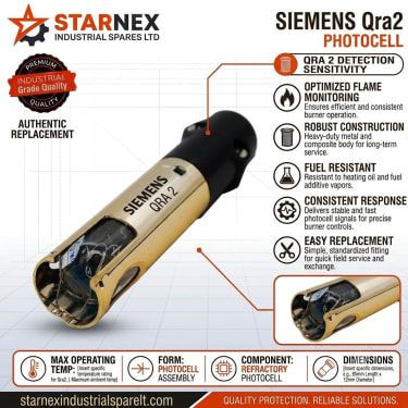
Of all the components on an industrial oil burner, the photocell is the smallest, cheapest, and most frequently misunderstood. It sits quietly inside the burner blast tube—a slender plastic cylinder no thicker than your thumb with two flexible wires running back to the control box base.
Yet when this tiny sensor is blinded by a thin film of soot, the largest steam boiler in a tea factory or processing plant will shut down instantly. The boiler operator stands in front of the machine, watches the ignition spark catch, sees a bright yellow flame roar inside the furnace for exactly four or five seconds, and then hears the fuel valve snap shut as the burner control box trips into safety lockout.
"The burner fires, but it won't stay on!" is the frantic call our Nairobi trade counter receives almost daily. In most cases, the burner is firing perfectly. The problem is that the control box is blind: it cannot see the flame it just created.
Understanding how photocell flame detectors operate, how to test them with a basic multimeter, and how to maintain optical alignment saves hours of diagnostic confusion.
How a Photocell Works: The Science of Photo-Resistance
Unlike thermocouple probes that generate millivolts through heat or ionization rods that rectify alternating current, standard oil burner photocells—such as the ubiquitous Siemens QRB1 series—are photo-conductive resistors.
Inside the tip of the sensor sits a semi-conductor crystal, typically Cadmium Sulfide (CdS). Cadmium sulfide possesses a unique physical property: its electrical resistance changes dramatically based on visible light exposure.
- •In Total Darkness: Free charge carriers inside the crystal are bound tightly. Electrical resistance across the two sensor wires is extremely high—typically exceeding 2 to 5 Mega-ohms (MΩ). At this resistance, practically zero current can pass back to the control box circuit.
- •Under Yellow Flame Light: Photons emitted by incandescent carbon particles in the diesel or light oil flame strike the crystal, releasing electrons. Electrical resistance collapses rapidly down to under 5 Kilo-ohms (kΩ). Current flows freely through the sensor, signaling the control box that a healthy flame is present.
If the sensor does not see sufficient light within the burner safety time $t_2$ (usually 5 to 10 seconds), the safety relay drops out, cutting electrical power to the fuel pump solenoid valve.
Dark vs. Light Resistance Bench Testing
Before condemning a control box or buying a replacement photocell, perform a quick bench test using any digital multimeter:
                  BENCH TESTING RESISTANCE WITH MULTIMETER:

      [ DARK TEST ]                                  [ LIGHT TEST ]
    Cover with Black Tape                         Aim at Flashlight / Sunlight
   ┌──────────────────────┐                     ┌──────────────────────┐
   │  Multimeter: > 2 MΩ  │                     │ Multimeter: < 5 kΩ   │
   └──────────────────────┘                     └──────────────────────┘
         ▲          ▲                                 ▲          ▲
         │          │                                 │          │
        [+]        [-]                               [+]        [-]
└──[QRB1]──┘ └──[QRB1]──┘| Sensor State | Test Condition | Target Resistance Value | Engineering Meaning |
|---|---|---|---|
| Healthy Sensor (Dark) | Sensor face covered with black tape | 2.0 MΩ to Infinity | Sensor proves no false light in standby |
| Healthy Sensor (Light) | Sensor exposed to ambient bulb / torch | 0.5 kΩ to 5.0 kΩ | Good sensitivity; proves flame presence |
| Soot-Coated Sensor | Exposed to torch light with dirty lens | 20 kΩ to 150 kΩ | Signal too weak to hold control box relay |
| Short-Circuited Sensor | Total darkness test | < 10 kΩ | Extraneous light lockout (4-blink fault code) |
| Burned-Out Element | Bright light test | Infinity / Over-Limit | Element open circuit; constant 2-blink lockout |
If the resistance remains above 20 kΩ under bright light even after cleaning, the internal photo-conductive wafer has aged or heat-fatigued. Replace the unit immediately.
Step-by-Step: How to Clean a Dirty Photocell Safely
In industrial boiler rooms burning heavy diesel or recycled oils in Kenya, soot deposition is inevitable. Every time a cold burner ignites, a microscopic layer of unburned carbon mist deposits on the optical glass.
Cleaning a photocell takes three minutes, but doing it improperly will destroy the lens:
- 1Isolate Electrical Supply: Switch off the burner control panel isolator.
- 2Extract Sensor: Grip the rubber mounting plug or retaining bracket and gently slide the photocell straight backward out of its guide tube in the burner housing.
- 3Inspect the Lens: Look at the front window. A healthy lens is crystal clear. A fouled sensor will have a brown, grey, or pitch-black soot coating.
- 4Clean the Optics:
- •DO: Use a soft, lint-free microfiber cloth moistened with pure isopropyl alcohol (IPA) or electrical contact cleaner.
- •DO NOT: Use petrol, brake fluid, or aggressive thinners, which melt acrylic plastic sensor heads.
- •DO NOT: Use wire brushes, razor blades, or emery paper; scratching the optical face creates light refraction that blinds the sensor.
- 1Clean the Sight Tube: Shine a flashlight down the hollow guide tube in the burner chassis. Make sure carbon flakes or dried fuel sludge have not accumulated inside the sight passage.
- 2Reinstall and Lock: Slide the sensor back into its retaining collar until it bottoms out against the factory stop.
Optical Alignment and Sightline Geometry
Cleaning the sensor is useless if the photocell is not actually looking at the flame. The sensor does not look through the center of the combustion chamber; it looks down a narrow sight path angled past the ignition electrodes and the diffuser plate.
                  BURNER BLAST TUBE OPTICAL SIGHTLINE:
                      Photocell Guide Tube
                       ┌──────────────┐
                       │  [QRB1 Sensor]
                       └──────┬───────┘
                              │ Sightline Angle (Must clear diffuser)
                              ▼
           ┌─────────┐      \
     [Fuel │ Burner  │       \    [IGNITION ARC]       [EXPANDING FLAME]
     Line]─┤ Nozzle  ├────────\───────- - - - - - - - - - - - - - - - -
           └─────────┘         \
                             [Diffuser Ring]
Common Alignment Defects Encountered in the Field:
- •Sensor Pushed in Too Shallow: If the rubber stopper is loose, the photocell can back out by two centimeters. The lens ends up looking at the dark inside wall of the guide tube rather than the flame root.
- •Diffuser Plate Rotated: During nozzle servicing, if the diffuser disc is reinstalled without aligning the sight notch, the solid metal blade of the diffuser will physically block the photocell's field of view.
- •Axial vs. Radial Orientation: Siemens manufactures the QRB1 with two viewing configurations: QRB1-A (radial side-viewing window with a black collar) and QRB1-B (axial front-viewing window with a red clamping ring). Installing a side-viewing sensor into a straight axial sight tube means the sensor stares directly at the steel pipe wall.
Diagnosing "Extraneous Light" Pre-Purge Lockouts
What happens when a burner locks out before it even tries to light? You press reset, the fan motor starts, pre-purges for fifteen seconds, and before the ignition transformer sparks, the box trips into lockout. On a Siemens LMO or LME controller, this registers as 4 Red Blinks.
This is an extraneous light fault. To prevent explosive puff-backs, the control box firmware mandates that the sensor must confirm darkness during the pre-purge cycle. If it detects light when no flame should exist, it aborts ignition.
Why Extraneous Light Occurs:
- 1Glowing Refractory Firebricks: In high-temperature steam boilers or refractory-lined kilns running at full load, shutting down the burner leaves the furnace bricks glowing incandescent red-yellow. If the burner restarts immediately, the photocell sees the glowing bricks and locks out. (Remedy: Increase pre-purge time or adjust sight angle away from the rear refractory wall).
- 2Open Inspection Flaps: If an operator unlatches the sight glass flap or leaves the burner cover off in a brightly lit boiler house, ambient light leaks into the blast tube.
- 3Internally Shorted Sensor Cable: If the high-voltage ignition cable rubs against the sensor wires, or if the sensor cable has been crushed by the burner housing, internal insulation leakage can mimic a closed circuit.
What Details to Provide STARNEX for Replacements
STARNEX stocks genuine Siemens, Satronic, and Brahma flame sensors at our Nairobi distribution center for same-day dispatch across Kenya and East Africa. When contacting our technical counter, provide:
- •Brand & Part Code: E.g.,
Siemens QRB1-A 050B70orSatronic FZ 711. - •Mounting Style: Specify whether your unit uses a flexible rubber plug collar, an aluminum bracket clamp, or a threaded brass bushing.
- •Cable Length: Standard replacement lengths are 350 mm, 500 mm, or 1000 mm with heat-resistant silicone jackets.
For urgent flame safeguard replacements or technical troubleshooting, contact our engineering desk at Enterprise Road, Nairobi via WhatsApp at +254 740 459 672.